What Is a Microcontroller?
A microcontroller (MCU) is a small, self-contained computer built into a single chip. It includes: One or more CPU cores, RAM and program memory (like Flash or ROM), Programmable I/O interfaces. Unlike general-purpose microprocessors, which require multiple separate chips for memory and I/O, microcontrollers are designed for embedded applications — compact, cost-effective systems that control specific tasks. While less powerful than a System on a Chip (SoC), a microcontroller may still be part of one. SoCs typically integrate more advanced components like Wi-Fi, GPUs, or coprocessors. Microcontrollers are found in countless devices — from car engines and medical implants to toys, appliances, and IoT edge devices. Their low cost, small size, and ability to handle both digital and analog signals make them ideal for controlling real-world systems efficiently.
For our project, we’re using two microcontrollers: the Arduino Nano and the ESP32-S3. The reason is simple. The Arduino IDE is incredibly easy to set up, and building and uploading code is much more straightforward than using Visual Studio Code with the ESP-IDF plugins. For example, it took me hours just to accept that the ESP Docker build environment wouldn’t work on my older iMac. I’m not giving up on it forever — just parking that battle for now. That’s why we’re starting with the Arduino for all the basic steps and concept testing. At this stage, it really doesn’t matter which microcontroller we use; the focus is on getting ideas working quickly and refining them later.
A typical microcontroller comes with around 38 pins (for example, 2 × 19). But not all of them are free to use — some are reserved for dedicated functions. Here’s a quick breakdown of what these pins can do:
- Power Supply Pins
5V / 3.3V — Provide regulated voltage to power components
GND — Ground reference for the entire circuit - Communication Interfaces
I²C (SCL / SDA) — Serial bus for connecting sensors and peripherals
SPI (MOSI / MISO / SCK / SS) — High-speed full-duplex communication
TX / RX — UART serial transmission and receiving - Analog-Digital Converter (ADC)
ADC pins measure analog voltage levels (e.g. 0–3.3V)
Values are mapped to a numeric range, commonly 0–255 or 0–1023, depending on resolution. This is useful for reading sensors like potentiometers, temperature sensors, or light levels. - Digital Output & PWM
Some pins support PWM (Pulse Width Modulation) — great for dimming LEDs or simulating analog signals. Others may allow Digital-to-Analog Conversion (DAC) in the opposite direction - GPIO — General Purpose I/O
GPIO pins can either output voltage (e.g. 0V or 5V) or read logic levels (true/false)
They’re the basic interface for buttons, LEDs, relays, and much more
Think of them as programmable switches — simple but powerful.
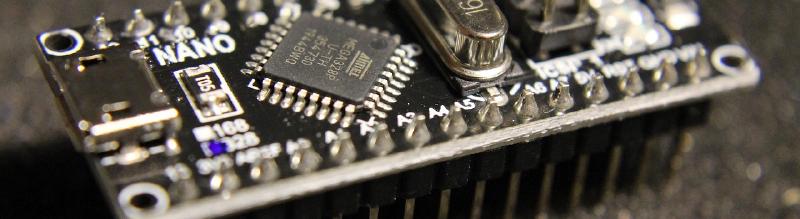
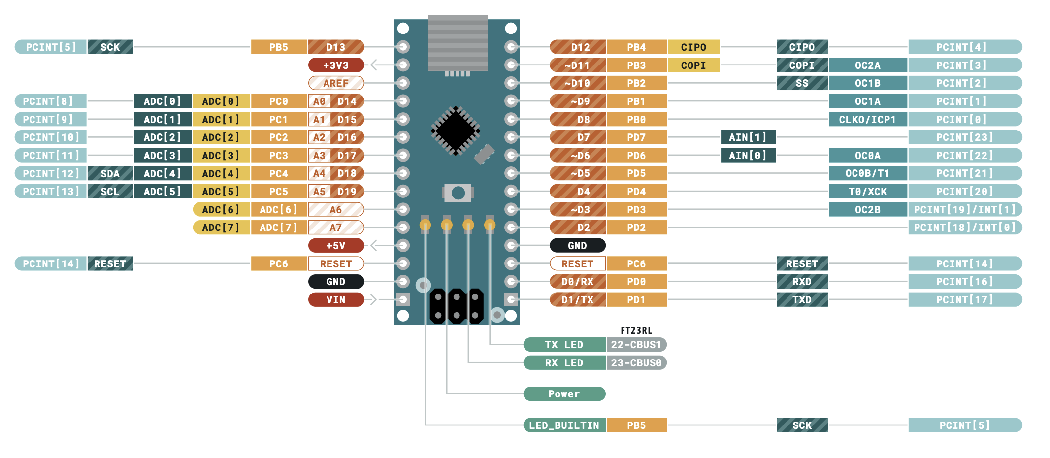
Pin Out
Arduino Nano
- Simple & beginner-friendly: Great for basic sensors, LED projects, small automation.
- Lower power & simpler architecture: Less computational power but easier to use.
- Limited connectivity: Needs external modules for Wi-Fi/Bluetooth.
Now that we’ve scratched the surface of an Arduino, you have multiple options to continue reading:
- Arduino overview to get a more basic Arduino foundation
- Arduino Processor basics take a deeper dive into the language of an AVR — the processor at the heart of an Arduino Nano
- AVR Cycles, Opcodes, Instructions In that deep dive, you’ll learn how to disassemble a high-level C++ program, and even decipher raw opcodes and instructions
ESP32-S3
- Much more powerful: Suitable for demanding applications and wireless communication.
- Integrated Wi-Fi & BLE: Out-of-the-box wireless connectivity.
- More peripherals: Extensive hardware interfaces and features such as USB OTG and external PSRAM support.
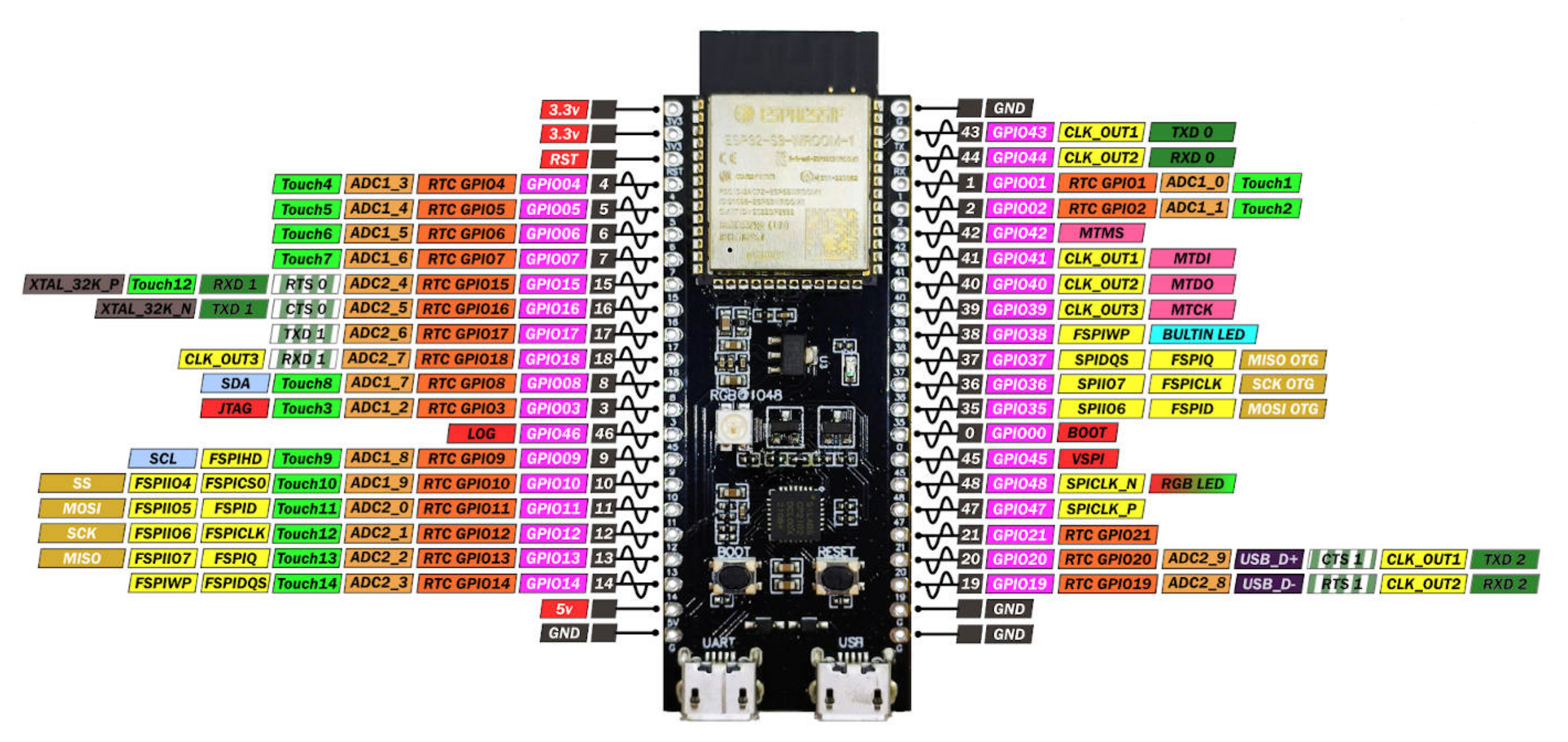
Website: ESP32
Comparison
| Feature | Arduino Nano | ESP32-S3 |
|---|---|---|
| Processor | ATmega328P (8-bit AVR) | Dual-core Xtensa LX7 (32-bit) |
| Clock Speed | 16 MHz | Up to 240 MHz |
| Flash Memory | 32 KB | Up to 16 MB (external) |
| SRAM | 2 KB | 512 KB |
| EEPROM | 1 KB | None (but flash or external options) |
| Operating Voltage | 5 V | 3.3 V |
| I/O Pins | 22 (14 digital, 8 analog) | ~34 GPIO (depending on package) |
| Analog Inputs | 8 | 20 (12-bit ADC) |
| PWM Outputs | 6 | Many (flexible on most pins) |
| Communication | UART, SPI, I2C | UART, SPI, I2C, CAN, I2S, etc. |
| Connectivity | None by default | Wi-Fi (802.11 b/g/n), Bluetooth LE |
| USB Support | Yes (mini USB) | Native USB OTG |
| Power Consumption | Low | Moderate to high (depends on features used) |
| Development Support | Arduino IDE, PlatformIO | Arduino IDE, ESP-IDF, PlatformIO |
| Typical Applications | Simple projects, basic I/O control | Advanced IoT, AI (with vector instructions), edge computing |